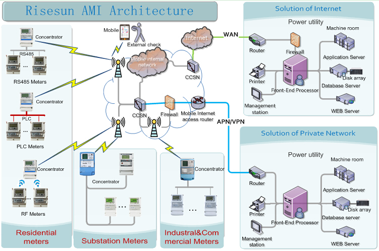


Advanced Metering Infrastructure (AMI) is the technology of automatically collecting data from energy metering devices and transferring that data to a central database by communication technology for remote control and analyzing. RS801E AMI system is composed of management software, remote communication channel, power management terminal, regional summary meter, local communication channel, user energy meter and other equipments. Power companies can build AMI system to replace the manual meter reading to save human resources, reduce meter reading costs and improve meter reading efficiency and success rate. The AMI system reduces the error rate, the electricity loss and eliminates the false meter reading by personnel. The AMI system also can monitor the status of the users and find the abnormal information to alarm in time. It also collects data from regional summary meter and the regional line loss can be calculated. The software system is developed by Java and it can be deployed on Windows, Unix, and other major operating systems. The system is developed based on Enterprise-class Jave EE standards, a three-tier technical architecture (client / middleware server / database server) as the basis for the system. The system has excellent openness, scalability, flexibility and high reliability. Many advanced computer and communication technologies are used on this AMI system to satisfy the needs of power companies in different environments.

